Stepper Motor Control
A common stepper motor is the four-coil unipolar. They are called unipolar because they require only that their coils be driven on and off. The stepping sequence for a four-coil unipolar steppers is shown below.
If you run the stepping sequence forward, the stepper rotates clockwise; run it backward, and the stepper rotates counterclockwise. The motor’s speed depends on how fast the controller runs through the step sequence.
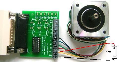
The stepper motor we used is the PF443-03A from Mycom. It requires a supply voltage of 12V and the coil current is 0.31A. Each step is 1.8 degrees.
The EMANT300 digital output current drive is about 20mA - too low to drive the stepper motor coil. Besides, the Mycom PF443 stepper motor operates from a 12V supply which is higher than the 5V allowed for the EMANT300 digital output. Therefore, one simple solution is to add the ULN2003. The ULN2003 is a high voltage, high current darlington driver comprising seven NPN darlington pairs. All feature integral clamp diodes for switching inductive loads. The ULN2003 has a maximum sustaining output voltage of 50V and maximum output current of 0.5A per channel which easily meet the requirements of the Mycom PF443 stepper motor.
Schematic
LabVIEW Front Panel
- Run the LabVIEW program EMANT300 Example Stepper Motor.VI
- Toggle Halt /Run switch to run.
- Changing the loop delay will change the motor speed
- Switch between Forward/Reverse makes the stepper to turn clockwise/anticlockwise
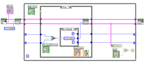
- From the block diagram, the
sequence of the digital output bits are
D3 D2 D1 D0 1 0 0 1 1 1 0 0 0 1 1 0 0 0 1 1 repeat
- Reversing the sequence changes the direction of rotation
LabVIEW Diagram